Electronic Measurement

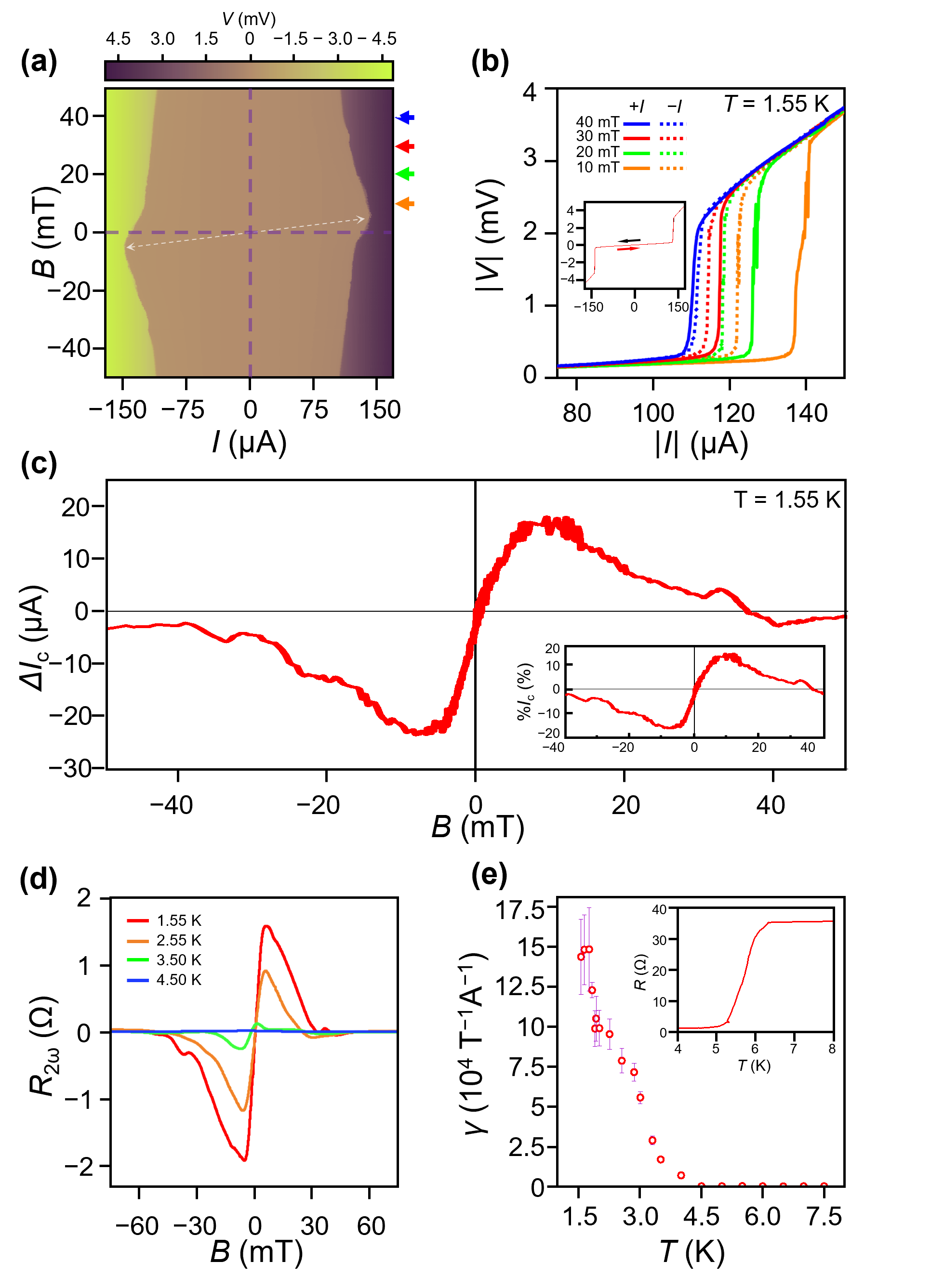
Figure 1 (a) Voltage drop across the NbSe2 layer with respect to the current and magnetic field at T=1.55 K. The nonreciprocity and magnetochirality appear as point symmetry, as indicated by the purple dotted line. (b) I-V line cuts of Fig. 3a at 10, 20, 30, and 40 mT. The solid and dotted lines indicate the positive and negative transports direction, respectively. The line cuts are plotted near Ic to highlight the nonreciprocity. The location of each curve in the colormap of Fig. 3a is marked with arrows of the same color. The inset shows the current-voltage characteristic with a different current sweep direction at B=0 T, where the arrows with the corresponding color indicate the current sweep direction. (c) Dependence of ΔIc on the applied magnetic field. The measurement was performed by sweeping the magnetic field from positive to negative. The inset shows the dependence of %Ic on the applied magnetic field. A maximum value of 16% was observed. (d) Magnetic-field dependence of the second-harmonic resistance. The magnetic field was swept from positive to negative. (e)Magnetochiral anisotropy γ was calculated from Fig. 2d with the corresponding error bar. The inset shows the temperature dependence of the resistance of the device.

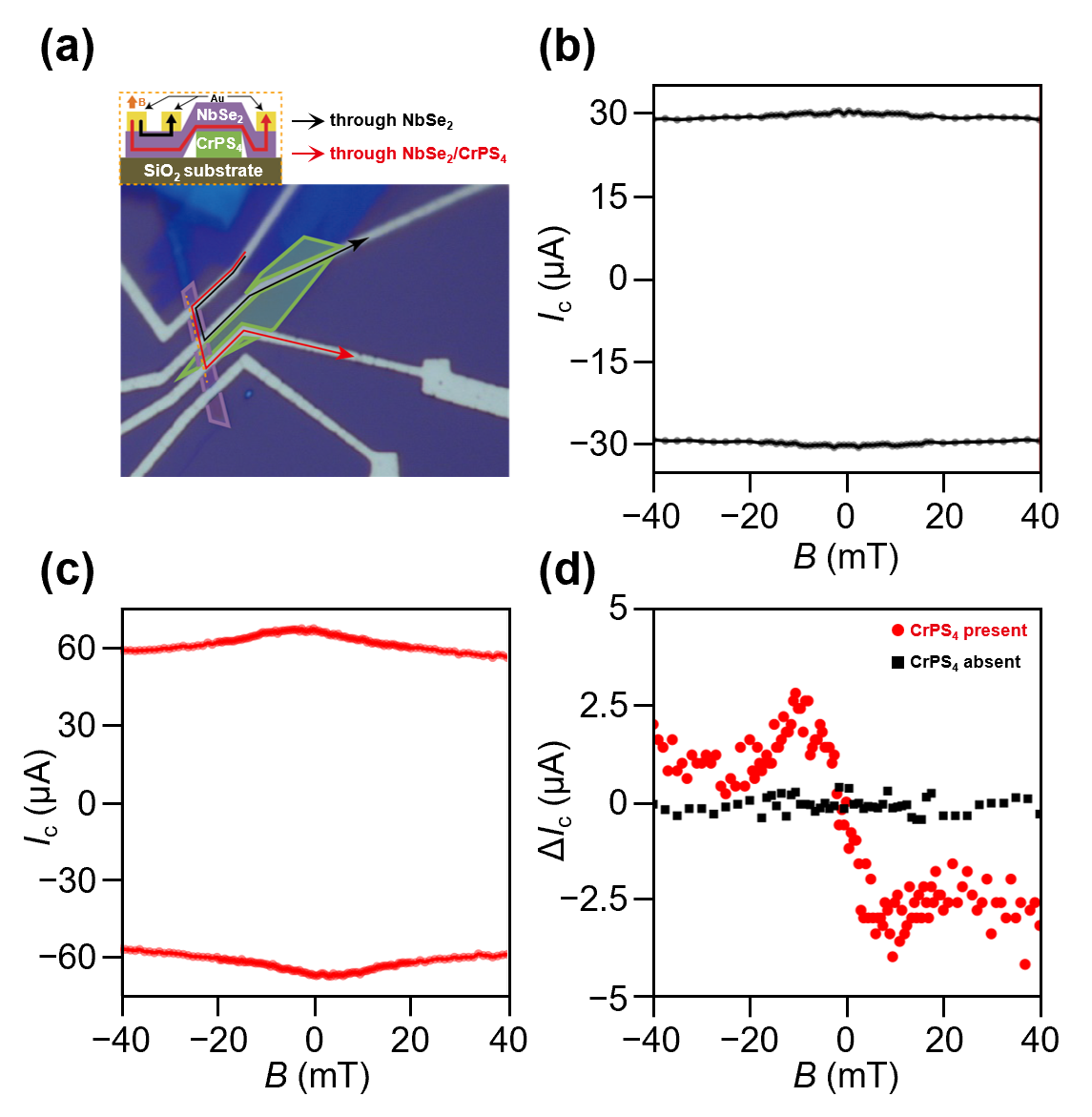
Figure 2 (a) An optical microscope image of the device, where the NbSe2 and CrPS4 layers are demarcated by purple and green lines, respectively. The black and red arrows indicate the current paths with and without the adjacent CrPS4. (b) The critical current Ic of the device when the current flows through NbSe2 layers without CrPS4. The current direction is indicated by the black arrow in (a). No superconducting diode effect is observed. (c) The Ic of the device when the current flows through NbSe2 in close contact with CrPS4 layers. The current direction is indicated by the red arrow in (a). A superconducting diode effect is observed. (d) The critical current difference ΔIc of the device when CrPS4 is present (red circle) and absent (black square). The correlation between the CrPS4 layer and the superconducting diode effect of NbSe2 can be clearly identified.

Electronic Measurement of van der Waals Devices

This page contains detailed information about the electronic measurement of van der Waals heterostructure. Specifically, the van der Waals device I measured throughout this project was NbSe2, which is in close contact with CrPS4. The detailed description can be found below.

Superconducting Diode Effect in a NbSe2/CrPS4 heterostructure

In this work, we realized a superconducting diode effect in a NbSe2/CrPS4 heterostructure. In this device, NbSe2 is exchange-coupled with a CrPS4 van der Waals layered antiferromagnetic insulator. The NbSe2/CrPS4 bilayer device exhibits bias-dependent superconducting critical-current variations of up to 16%, with the magnetochiral anisotropy reaching ~105 T-1A-1. Furthermore, the CrPS4/NbSe2/CrPS4 spin-valve structure exhibits the superconducting diode effect with critical-current variations of up to 40%. We also utilize the magnetic proximity effect to induce switching in the superconducting state of the spin-valve structure. It exhibits an infinite magnetoresistance ratio depending on the field sweep direction and magnetization configuration. For the representative results of this project, please refer to Figure 1 and 2 and you can find details at Phys. Rev. Research 5, L022064.